Calculating the Wedges Centre of Gravity.
“A Weighty Problem”
Were we to suspend an object by its Centre of Gravity, we could move that object to any orientation with just a feather light touch. Locating the Center of Gravity (CG) in three dimensions (length, Width and height) is an important first step to analysing many aspects of a vehicles performance, especially the handling characteristics. For instance, the length and height dimensions are important when analyzing anti-dive and anti-squat suspension geometry. The width and height dimensions can also tell us a lot about a vehicles roll-over properties.
In order to calculate the length and width dimensions of the centre of gravity the vehicle will need to be weighed on a level surface. Usually this entails measuring the weight under each wheel. To find the height dimension of the center of gravity, the vehicle will need to be raised (up to a maximum of 45 degrees from horizontal) at one end and the weight under each wheel measured while in the raised position.
Note: The usual care and attention to safety should be exercised to avoid turning this fun and educational exercise into a catastrophe. Be careful when lowering the wheels onto the scales, so as not to push the scale sideways thus binding the mechanism and producing a false reading. Systems of scales are available for measuring the corner weights of race cars and are usually designed to compensate for the sideways movement of the suspension. If you have difficulty finding bathroom scales that are rated to 800lbs, try looking around at the local performance car club scene. Some of the more serious racer oriented clubs may just have a set for members to use. Shops that setup race cars or performance street suspensions may also have a set of scales.
With reference to the various figures that follow, we need to first measure the values of the variables in the table below:
|
Variable |
Description |
|
|
|
|
Dwb |
Wheel Base - measures the distance between front and rear wheel centres. This can be accomplished by suspending a plumb-bob from the centre of each axle and measuring between the suspended lines. |
|
Dtk |
Track - measures the distance between the centres of the front tyre ground contact patches. Note for our purposes we assume that the front and rear tracks are equal, or we take an average. |
|
Wfl |
Weight under the front left wheel, when vehicle is at rest. |
|
Wfr |
Weight under the front right wheel, when vehicle is at rest. |
|
Wrl |
Weight under the rear left wheel, when vehicle is at rest. |
|
Wrr |
Weight under the rear right wheel, when vehicle is at rest. |
|
Dup |
The height that both rear wheels are lifted off the ground. For convenience and accuracy, this should be measured between the rear wheel centre and the ground. Usually a lift height of 12-16 inches is the maximum necessary to achieve usable results. |
|
Dwbup |
The Wheel Base in the raised position - measures the horizontal distance between front and rear wheel centres once the vehicle is lifted by height of Dup. Dwbup should in all cases be less than Dwb. The measurement can be accomplished in the same way as before, by suspending a plumb-bob from the centre of each axle and measuring between the suspended lines. |
|
Wflup |
Weight under the front left wheel after lifting the rear wheels by height Dup |
|
Wfrup |
Weight under the front right wheel after lifting the rear wheels by height Dup |
|
Wrlup |
Weight under the rear left wheel after lifting the rear wheels by height Dup |
|
Wrrup |
Weight under the rear right wheel after lifting the rear wheels by height Dup |
|
Dwr |
Distance of the centre of the axle to the ground, when the vehicle is at rest and sitting level on the ground. |
|
|
|
Table 1
Length and Width Dimensions
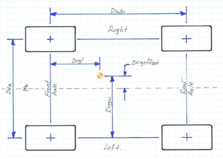
Figure 1
With reference to Figure 1, the distance Dcgl as defined by Equation 1, represents the length co-ordinate of the Centre of Gravity.
|
Equation 1: |
Dcgl = |
Dwb * Wrear |
|
|
|
Wfront + Wrear |
Where: Wfront = Wfl + Wfr and Wrear = Wrl + Wrr.
The distance Dcgw as defined by Equation 2, represents the width co-ordinate of the Centre of Gravity.
|
Equation 2: |
Dcgw = |
Dtk * Wright |
|
|
|
Wleft + Wright |
Where: Wright = Wfr + Wrr and Wleft = Wlf + Wlr.
From a practical perspective it may be easier to find the centreline of the vehicle and measure an offset. This can be done by calculating DcgwOffset as follows:
|
Equation 3: |
DcgwOffset = |
Dcgw – ( Dtkf / 2 ) |
|
|
|
|
Note: that if the result is negative we measure left of the longitudinal centre line. A positive result is measured to the right of the centre line as drawn in figure 1.
Height Dimension
This one is a little more complicated, but the way it is calculated has been around for years and essentially requires that we assume that the vehicle is a solid object and that the CG doesn’t move, within that object, regardless of the orientation that the object is held at. Since we can’t measure the height of the CG with just a tape measure, we rather cleverly measure instead the effect of a known change in the orientation of the whole object. To achieve the most accurate results the suspension should be immobilized as much as possible because either compression or extension of the springs may affect the CG location.
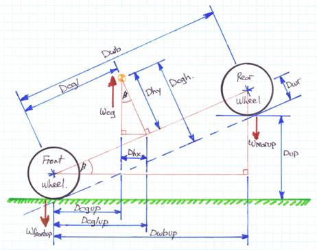
Figure 2
Table 1 and Figure 2 give some idea of what is going on and Equation 4 defines Dcgh, which represents the height of the Centre of Gravity above the ground.
|
Equation 4: |
Dcgh = |
( Dcgl * Dwbup ) |
+ |
(( Dwbup * Wrearup ) * Dwb ) |
+ Dwr |
|
|
|
Dup |
|
Dup * ( Wfrontup + Wrearup ) ) |
|
Weight Distribution
I don’t think there has ever been a performance car review written that didn’t mention weight distribution. To calculate the front weight distribution (%) we simply divide the weight over the front wheels by the total vehicle weight as follows:
Equation 5: % Front weight distribution = (Wfl + Wfr ) / Wtotal * 100%
Likewise the equation for the rear weight distribution is as follows:
Equation 6: % Rear weight distribution = (Wrl + Wrr ) / Wtotal * 100%
Where: Wfrontup = Wflup + Wfrup and Wrearup = Wrlup + Wrrup.
Mandatory Wedge content
So much for the general theory. It’s now time to sharpen our pencils and get
down to business. First we need to gather the base data. All the distance
dimensions in table 2 were taken from the TR8 Repair Operations Manual (ROM,
aka the “Red” manual). Real world vehicle corner weights were kindly provided
by Dave Massey for his TR8 convertible. Dave did not have the opportunity to weigh
his car in the raised position so only the longitudinal and transverse CG
dimensions can be calculated for this article.
|
Variable |
Measurement |
Variable |
Measurement |
|
|
|
|
|
|
Dwb |
2160mm ( 85in )
|
Dwbup |
n/a |
|
Dtk |
1409mm ( 55.5in ) Note rear track = 1404mm ( 55.3in ) |
Dwr |
n/a |
|
Wfl |
322.5kg ( 711lb ) |
Wflup |
n/a |
|
Wfr |
346.9kg ( 765lb ) |
Wfrup |
n/a |
|
Wrl |
246.3kg ( 543lb ) |
Wrlup |
n/a |
|
Wrr |
247.6kg ( 546lb ) |
Wrrup |
n/a |
|
Dup |
n/a |
|
|
|
|
|
|
|
Table 2
First a quick sanity check on the data:
Substituting into the weight distribution equations:
Front = ( 322.5kg + 346.9kg ) / 1163.3kg * 100 % = 57.54%
Rear = ( 246.3kg + 247.6kg ) / 1163.3kg lb * 100% = 42.46%
These weight distribution results compare favourably with the data published in dealer brochures and magazine reviews back when the vehicles were new, so we can assume that our data is in the correct ball park.
Plugging data into the Centre of Gravity equations:
Wfront = 322.5kg + 346.9kg = 669.4kg ( 1476lb )
Wrear = 246.3kg + 247.6kg = 493.9kg ( 1089lb )
Wleft = 322.5kg + 246.3kg = 568.8kg ( 1254lb )
Wright = 346.9kg + 247.6kg = 594.5kg ( 1311lb )
|
Dcgl = |
2169mm * 493.9kg |
= |
920.9mm ( 36.25in ) |
|
|
669.4kg + 493.9kg |
|
|
Or, if you find it easier to measure from the centre of the rear wheel/axle: Dwb – Dcgl = 1243mm ( 48.9in )
|
Dcgw = |
1409mm* 594.5kg |
= |
720.1mm ( 28.35in ) |
|
|
568.8kg + 594.5kg |
|
|
Converting to an offset from the vehicles centre line:
|
DcgwOffset = |
720.1mm |
- 1409mm |
= |
15.6mm ( .61in ) |
|
|
|
|
|
2 |
|
|
||
Conclusion
There you have it. We see that the Centre of gravity for Dave’s car is located approximately 920mm behind the front axle centre line and 16mm to the right (passenger side) of its centre line. We also know that this vehicle ( as weighed ) has an approximate front/rear weight distribution of 57.5%/42.5%.
By plugging a number of relatively simple measurements into three equations, we can determine (in theory) the exact location of the centre of gravity of any four wheeled vehicle.
To make this a more scientifically accurate and useful exercise, we’d have to document the conditions under which the measurements were made. Some suggestions would be to make the measurements without onboard luggage or tool boxes etc., with the fuel tank full and empty, with and without a driver, with and without A/C, measuring the ride height (lowered springs have an effect) etc. Also in order to build a suitable knowledge base, it would be beneficial to combine the conditions mentioned across a selection of TR7’s and TR8’s in both coupe and convertible body styles.
Thank you
I’d like to thank Dave Massey for providing real corner weight measurements from his convertible TR8.
Author: Mark Elbers
Disclaimer: I’m not an engineer, just a guy with access to relevant technical documentation and a sense of curiosity. This article presents my thoughts, based on the research and general reading that I’ve performed on this topic. If you find errors in my work I would appreciate hearing from you. I can be contacted through the WWWEDGE e-mail list (tr8@mercury.lcs.mit.edu).
Copyright © M Elbers, 2010 - 2016. All Rights Reserved