Wedge Anti-Dive
"To dive or not to dive, that is the question”
( Disclaimer: I’m not an expert on suspension theory or the mathematics used in this article. The mathematical suspension model presented is based on a number of simplifying assumptions and my rather limited knowledge of geometry and trigonometric functions. It is therefore at best an approximation of reality and should be used with caution. )
In part one I showed how to calculate the location of a vehicle’s centre of gravity. In this article I try to demonstrate an analysis of several ways to adjust the anti-dive behaviour on the Wedge. I also attempt to answer the question of “How much anti-dive is appropriate” To define what anti-dive is, I’ll rely on a couple of quotes lifted from page(s) 146-147 of the book “Racing Car Design and Development” by Len Terry and Alan Baker. Baker writes:
“Modifying the suspension geometry to reduce braking-dive or acceleration-squat, due to weight transfer, is no new idea.” .... “There are two basic methods of obtaining anti-dive and anti-squat (which is the same thing in reverse). The first is to converge the axes of each pair of wishbones, as viewed from the side. This convergence is towards the rear for the front wishbones and vice versa. In theory, if the convergence points coincided on the transverse axis through the centre of gravity, no diving or squatting moment would be created. Such a layout would be impracticable, but the same result can be achieved by having the convergence points (which are the instantaneous centres of the ‘equivalent’ leading and trailing arms) on the lines joining the tyre contact points to the transverse axis through the centre of gravity.”
Both anti-dive and anti-squat are normally described as a percentage of the height from the road surface relative to the height of the centre of gravity. With reference to figure 1, you’ll see that the example shows the second method, mentioned above, with 50% anti-dive and 100% anti-squat. The diagram is meant to be illustrative and not to scale. It is rare that a vehicle would have even 25% anti-dive.
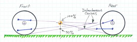
Figure 1
When analysing the Wedge’s front suspension, it is relatively easy to see how the Track Control Arm (TCA) and front sway bar form the familiar triangular lower wishbone assembly. However it is at the top of the suspension unit that a little logic needs to be applied, in order to define what may be described as a ‘virtual’ wishbone.
Looking at Figure 2, we can see that on wheel bump the axle (wheel centre) travels a path bounded by the TCA, sway bar and top of the strut. It makes sense therefore that the top wishbone would act perpendicular to the strut itself. The top converging link therefore is also located at the top of the strut, which is much higher than normal “dual wishbone” practice. The angle that the strut makes to the perpendicular is directly related to the caster angle and changes depending on the angle that the strut makes with the lower wishbone assembly. This implies that the caster angle may also change as the suspension bumps or droops.
Before continuing it is important to note that the following assumptions were made in developing the suspension model:
1. Unless otherwise specified, all calculations are based on a vehicle at rest on a level road surface.
2. The TCA is horizontal to the road surface and therefore the centers of the inner sub-frame bushing and the outer ball-joint are at the same distance “F” from the ground. This may not be the case with shorter road springs where the ball-joint may end up higher than the inner bushing.
3. The stub axle lies on a vertical line, perpendicular to the road surface that passes through the centre of the TCA sub-frame bushing. The tyre contact patch is therefore also centred under the TCA. In “real life” the axle would be slightly behind the TCA due to caster angle.
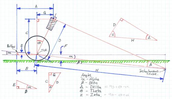
Figure 2
With reference to the various figures, we need to generate values for the following variables:
Note: I’ve included a number of “modifier” variables to allow for experimentation with both factory and aftermarket suspension modifications. See variables “A”, “C”, “E” and “F” for further explanation.
|
Variable |
Description |
|
|
|
|
Abase |
Horizontal distance from the centre of the roll-bar to the centre of the strut top pivot point. The distance “A” from the TR7 ROM (77.01.02) minus half the Distance “2” from the TR7 ROM (76.10.04) |
|
Castermod |
Modifier - Distance that strut top is moved forward or aft in the “G” direction in order to change the caster angle. Moving the top of the strut forward produces a negative value which decreases caster and moving it backward produces a positive value and increases caster. |
|
A |
Horizontal distance from the centre of the roll-bar to the centre of the strut top pivot point. A = Abase + Castermod |
|
B |
Horizontal distance from the centre of the roll-bar to the centre of the TCA sub-frame bushing. Distance “6” + “3” + ( “2” / 2 ) from the TR7 ROM (76.10.04) |
|
Cbase |
Early TR7 Coupe – Base vertical distance from the centre of the TCA sub-frame-bushing to the centre of the strut top pivot point. The distance “c” from TR7 ROM (77.01.02). |
|
TR8spacer |
Modifier – compensates for the 4 TR8 sub-frame spacers included to lower the sub-frame for V8 Carburettor bonnet clearance. Normally 12mm (.472 in) thick. |
|
C |
The vertical distance from the centre of the TCA sub-frame bushing to the centre of the strut top pivot point. C = Cbase + TR8spacer |
|
D |
The distance along the strut (side view), measured from the TCA sub-frame bushing to the c entre of the strut top pivot point. |
|
Ebase |
Early TR7 Coupe – Base vertical distance between centre of the roll-bar to the centre of the TCA sub-frame bushing without any additional roll-bar mount spacers. |
|
Stockspacer |
Modifier - Compensates for UKC 9883 – Measured at 6.8mm (.267in) |
|
rollbarmod |
Modifier - compensates for additional commercially available “performance” anti-dive spacers. Spacers have been measured at 2.54mm ( 1in ) thick. |
|
E |
Total Vertical distance between the centre of the roll-bar to the centre of the TCA sub-frame bushing. E = Ebase + Stockspacer + rollbarmod |
|
Fbase |
Early TR7 coupe – Base vertical height, (ie the ride height) between the road surface and the centre of the TCA sub-frame bushing. |
|
Springmod |
Modifier – compensates for ride height due to modified road springs as measured at the TCA subframe bushing. A positive value increases the ride height as found on some rally cars and a negative value decreases ride height as found on tarmac race cars. |
|
F |
The height, from the road surface to the centre of the TCA sub-frame bushing. F = Fbase + Springmod – TR8spacer |
|
G |
Horizontal distance between the centre of the TCA sub-frame bushing to the centre of the strut top pivot point. |
|
H |
Distance from the centre of the TCA sub-frame bushing to the instantaneous Centre of the front suspension. (Hypotenuse of the triangle) |
|
Hx |
Horizontal distance from the centre of the TCA sub-frame bushing to the instantaneous centre. |
|
Hy |
Vertical distance from the centre of the TCA bushing to the instantaneous centre. |
|
Dcgl |
Horizontal distance from centre of TCA bushing to centre of Gravity (assuming TCA and Wheel Centre fall on the same vertical line perpendicular to the road surface.) |
|
Dcgy |
Vertical distance from ground to point of intersection between the line joining the tyre patch to the instantaneous centre and the vertical perpendicular line through the centre of gravity. |
|
|
|
|
Angles |
Description |
|
Alpha |
Angle between the horizontal line through the centre of the inner TCA sub-frame bushing and the line through the centre of the inner TCA sub-frame bushing and the centre of the roll-bar. |
|
Beta |
Temporary angle used to derive the formula for Dcgy. |
|
Delta |
Angle at the Instantaneous centre. |
|
Theta |
Caster angle. Specifications in the ROM show 3.5degree plus or minus 1 degree |
|
Zeta |
Angle formed between the body of the strut and the line drawn through the TCA subframe bushing and the Instantaneous centre. |
|
|
|
Table 1
Note: that where mention is made of the TR8 Repair Operations Manual (ROM), I referenced the Red TR8 ROM, (Publication Part number: AKM 3971). Mention of the TR7 ROM refers to the Bentley official repair manual, (Printed 1981). A quick comparison to data provided in both the TR8 ROM, TR7 ROM and the Haynes TR7 manual showed general agreement in the published body dimensions and no discernable difference between TR7 or TR8, convertible or coupe, except that the TR8 showed an additional 12mm (.47in) in dimension “C” due to the addition of Front sub-frame spacers. (see 77.01.22 in both TR7 & TR8 ROMs)
Base Chassis Design
I chose this as the first case study, because it represents the suspension as it was originally designed. As a TR7 coupe without the TR8 front sub-frame spacers, front anti-roll bar spacers or any of the popular performance upgrades of lowered road springs or additional spacers under the front anti-roll bar mounts.
With reference to figure 2 and table 1, the value for each variable is derived as follows:
Abase = 347mm – ( 74mm / 2 ) = 310mm ( 12.20in )
Castermod = 0mm
A = Abase + Castermod = 310mm + 0mm = 310mm ( 12.20in )
B = 78mm + 171mm + ( 74mm / 2 ) = 286mm ( 11.26in )
Cbase = 571mm ( 22.48in )
TR8spacer = 0mm
C = Cbase + TR8spacer = 571mm + 0mm = 571mm ( 22.48in)
Theta = arctan( (A - B) / C ) = arctan ( (310m – 286mm ) / 571mm ) = 2.4 degrees
D = C / Cos( Theta ) = 571 / Cos( 2.4 ) = 571.5mm ( 22.50in )
Ebase = measurement = 11mm ( .43in )
Stockspacer = 0mm
Rollbarmod = 0mm
E = Ebase + stockspacer + rollbarmod = 11mm + 0mm + 0mm = 11mm ( .43in )
Fbase = measurement = 152.4mm ( 6in ) (derived from a measurement received from Bill Derksen)
Springmod = 0mm
F = Fbase + Springmod –TR8spacer = 152.4mm + 0mm - 0mm = 152.4mm
Alpha = arctan( E / B ) = Arctan( .43mm / 286mm ) = 2.2 degrees
Delta = 180-90- (90 – Theta + Beta) = 180 – 90 – ( 90 – 2.4 + 2.2) = .2 degrees
Changing our reference to figure 3:
H = D / Sin( Delta ) = 584 / Sin ( 1.3 ) = 160345.7mm ( 6312.82in )
Hx = H * Cos( Beta ) = 160345.7mm * Cos( 2.2 ) = 160227.2mm (6308.16in )
Hy = H * Sin (Beta ) = 160345.7mm * Sin ( 2.2 ) = 6162.6mm ( 242.62in )
Note: To put this in perspective, Hx can be represented in wheelbase lengths, calculated as Hx/Dwb = 160227mm / 2160mm = 74.
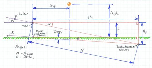
Figure 3
Dcgl = 914.2mm ( 35.88in ) (taken from the previous center of gravity article)
Tan( Beta ) = Dcgy / Dcgl = F-Hy / Hx
Solving for Dcgy:
Dcgy = (( F - Hy ) / Hx) * Dcgl
Due to some peculiarities of the Tangent function and the way I setup the TCA as a central point in the model Dcgy is defined by the following conditional statement:
IF ( F – Hy ) < 0
then Dcgy = -1 * ( ABS( F – Hy ) / Hx ) * Dcgl
otherwise Dcgy = ( ( F – Hy ) / Hx ) * Dcgl
Where ABS() is the Absolute Value function.
In this case Dcgy = -1 * ( ABS( 152.4 – 160227.2) ) /160227.2mm * 914.4mm = -34.4mm ( -1.35in )
Note: since we didn’t have sufficient data to calculate the height of the centre of gravity, I’ll substitute Dcgh = 304.8 mm (12 in) which is more of a guesstimate.
% Anti-dive = ( Dcgy / Dcgh ) * 100% = ( -34.4mm / 304.8mm ) * 100% = -13%
There you have it, the point where the line through the center of the tyre contact patch and the Instantaneous centre crosses the transverse axis through the centre of gravity is located approx 35mm (Dcgy) below the road surface. The Instantaneous centre is itself located 74 wheelbase lengths behind the front axle. Since zero anti-dive is defined as the point level with the road surface, does this indicate that the stock suspension is actually promoting dive under braking? Certainly many owners have observed that the stock wedge exhibits considerable dive under braking, so these calculations seem to support the empirical evidence.
Caster angle
Using the chassis dimensions in the ROM, we get a base caster angle of 2.4 degrees. It is interesting to note that the alignment card for both TR7 and TR8 calls for 3.5 degrees of caster, plus or minus 1 degree. What effect does that 2 degree spread produce? With reference to triangle CDG in figure 2, you’ll see that if we make the top of the strut adjustable in a fore and aft direction, variables “A” and angle Theta will change. Variable “C” remains unchanged.
The caster angle represented by Theta will change automatically in the suspension model once we set castermod to anything but zero. Note that a forward change should be a negative value and a rearward movement should be positive. Also note that to make such a change on the vehicle itself would require the elongation of the three strut top mounting holes, or the installation a camber/caster plate.
Making changes to the base configuration, we see that a caster angle of 2.5 degrees requires a castermod setting of 1mm and produces -34mm (Dcgy) anti-dive. A caster angle of 4.5 degrees requires a change a castermod setting of 21mm and produces -25.5mm (Dcgy) anti-dive. Given the distance that the strut top needs to be moved (20mm) in order to effect the anti-dive and the compromises that an in appropriate caster angle produces to handling, I would suggest that this is not an effective means of inducing anti-dive.
Front Sub-frame spacers
The complementary situation to changing the caster angle, is the case of the TR8 sub-frame spacer. These were installed at the factory to increase engine to bonnet clearance over the rather unique Stromberg Carburettor setup. There is some thought that the spacers were also designed to produce a more effective wheel camber curve, a lower front roll-centre and lower centre of gravity, but I suspect that those outcomes may have been more side effects rather than designed effects.
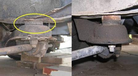
Figure 4
With reference to figure 4, the picture on the left shows the TR7 configuration consisting of one thin washer between the rubber bushing and the underside of the frame rail. On the right the washer is replaced with a much thicker (rusty) spacer. It is clear to see how the sub-frame is now lower relative to the frame rail above. These spacers lower the sub-frame and with it the front anti-roll bar and the TCA. The relationship between the front anti-roll bar and TCA does not change, because all four spacers are the same thickness. Lowering the TCA does change the caster angle, which as we’ve seen in the previous case does affect the percentage of anti-dive.
Referring again to triangle CDG in figure 2 we see that lowering the sub-frame increases variable “C” but leaves variable “G” unaffected. If all other parameters remain unchanged the variable “F” also decreases with an increase in “C”. The caster angle represented by Theta will change automatically in the suspension model when the variable TR8spacer is changed to a non-zero value. A normal value for TR8spacer is 0mm for the TR7 and 12mm for the TR8. Setting TR8spacer to 12mm did not change the caster angle of the base configuration significantly.
Note: Some people have suggested that the sub-frame spacers also lower the vehicle ride height, but in reality this does nothing to significantly change the length of the strut/spring, assembly, so ride height doesn’t change. Minimum ground clearance is reduced, but that in itself has no real effect on static suspension geometry, until the lowered cross-member hits something (like a speed bump) sticking out too far, above the road surface. Camber pattern may also change, but that is outside the scope of this article.
Lowered Road springs
We often hear of vehicles that have been lowered for performance reasons. Normally these springs not only lower the car, but also increase the spring rate to avoid issues resulting from the lower ride height. There has been much debate, whether wedges suffer from sagging road springs as the vehicles age. In 2015, Jim Tencate of the TWOA performed a scientific analysis of a number of sample factory springs (which were over 30 yrs old) and came to the conclusion that if those springs tested were a representative sample, they mostly performed within design specification and spring sag was not an issue that wedge owners needed to be worried about. Yet, wedge owners continue to report lowered ride height, especially in the front suspension.
In the suspension model, a change in the compressed length of the road spring will affect the “F” variable, which represents ride height of the TCA. This variable will change automatically if we set the variable Springmod to anything but zero. For example if we assume that performance springs have been installed that result in a 2.54 cm ( 1in ) reduction in ride height, we just set the variable Springmod = -25.4mm which results in -34.8mm (Dcgy) anti-dive. The installation of these, same, lowered road springs results in a .2mm lower anti-dive position, which indicates an increased tendency to dive under braking. Lowered road springs, by their design, usually have a higher spring rate and therefore contribute to a decreased forward dive. It could therefore be argued that any increase in anti-dive due to stiffer front road springs may be more accurately thought of as a brute force opposition of forces and therefore I haven’t included this effect directly in my suspension model.
Anti-roll bar Spacers
So far I’ve looked at a number of ways to modify the wedges front suspension geometry and none have really resulted in a significant increase in anti-dive geometry. However, all that is about to change.
The figure
below illustrates the difference in the way that the front anti-roll bar was
mounted between the early TR7 coupe and the later TR7’s and TR8’s. Based on
this information I initially assumed that later cars received an additional
spacer (UKC 9883)
between the anti-roll bar clamp and the sub-frame. Subsequent consultation on
the WWWedge e-mail list, indicates that most wedges received this modification
at the factory.
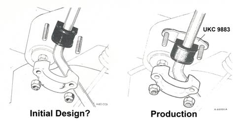
Figure 5
At some point, after-market performance suppliers began selling an additional spacer block designed to increase anti-dive in the front suspension geometry. In fact these spacers are often referred to as anti-dive spacers. The modification is not unique to our wedges, since the European Ford Capri and a number of small BMW’s used a similar suspension design through the 1970’s. Figure 6 shows views of the aftermarket spacer both on the vehicle (left picture) and off the vehicle alongside the factory UKC 9883 (right picture).
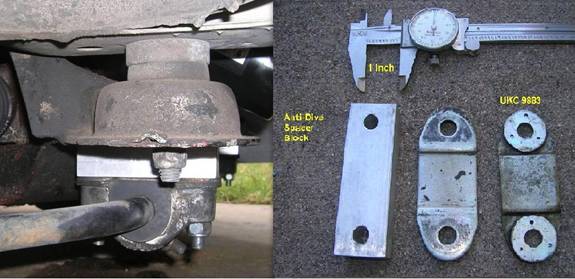
Figure 6
There is some debate whether the addition of the aftermarket spacer is necessary or even if it is possibly dangerous. In December 1980 Richard Hurdwell of the BL Motorsport Department in Abingdon, produced a report for the factory detailing the results of testing a pre-production TR8 for the UK and European Market. In his report, he recommended that doubling the stock anti-dive spacer (UKC 9883) would improve (increase) the anti-dive of the TR8, but he also recommended a shorter set of road springs.
In my suspension model the factory spacer is represented by the variable Stockspacer and thanks to Jim Tencate we know that it is 6.8mm ( .27in ) thick. The aftermarket spacer is represented by the variable Rollbarmod and is typically available in a 25.4mm ( 1in ) thickness. Entering these values into the suspension model for a TR7 results in the following:
The factory spacer contributes significantly to increased anti-dive (-34.7mm (Dcgy) without, -7.6mm with one spacer installed). On a stock TR7 suspension a 8.5mm thick spacer is all that is required to achieve zero anti-dive. Doubling up the stock spacers (as per Hurdwell’s recommendation) produces 19.4mm above ground. The aftermarket anti-dive spacer added to the stock spacer produces 93.4mm anti-dive. If we had accurate CG height data, we’d be able to calculate a % measurement for each of these values.
Note: the aftermarket anti-dive spacers are generally designed to work with the factory anti-dive spacer. To see what I mean, look at the rubber bushing. It extends above the rollbar clamp. Without factory spacers there is a recess in the cross-member to receive and presumably locate the bushing. The aftermarket spacers generally have no recess. To use the aftermarket spacer by itself would require the addition of that recess.
Figure 7 shows an example of a custom spacer design by Odd Hedberg, which effectively deletes the factory spacer at the same time. You can see clearly the machined recess for the bushing that matches the factory spacer configuration.
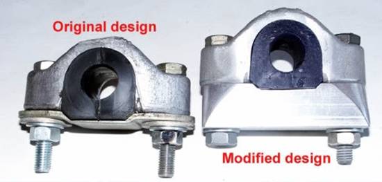
Figure 7
Mixing it up
Thus far, I’ve addressed each of the modifications in isolation from the others. So what happens if we add more than one modification at a time? In table 2 I’ve compiled the results of applying a number of common suspension combinations through the suspension model. The top rows show stock road spring length, whereas the lower rows show 1 inch lowered road springs.
Note: the TR7 column assumes stock TR7 sub-frame attachment, where as the TR8 column assumes the addition of the 12mm sub-frame spacers.
|
Configuration |
Stockspacer (mm) |
Rollbarmod (mm) |
Springmod (mm) |
TR7 Anti-dive (Dcgy) (mm) |
TR8 Anti-dive (Dcgy) (mm) |
|
Without spacers |
0 |
0 |
0 |
-34.4 |
-34.7 |
|
One factory spacer |
6.8 |
0 |
0 |
-6.8 |
-7.6 |
|
Two factory spacers |
6.8 |
6.8 |
0 |
20.8 |
19.4 |
|
One factory Spacer & after market spacer |
6.8 |
25.4 |
0 |
96.4 |
93.4 |
|
After-market spacer alone |
0 |
25.4 |
0 |
68.8 |
66.4 |
|
Zero anti-dive (TR7) |
0 |
8.5 |
0 |
0 |
n/a |
|
Zero anti-dive (TR8) |
0 |
8.7 |
0 |
n/a |
0 |
|
|
|
|
|
|
|
|
Without spacers |
0 |
0 |
-25.4 |
-34.6 |
-34.8 |
|
One factory spacer |
6.8 |
0 |
-25.4 |
-7.9 |
-8.7 |
|
Two factory spacers |
6.8 |
6.8 |
-25.4 |
18.8 |
17.4 |
|
One factory Spacer & after market spacer |
6.8 |
25.4 |
-25.4 |
91.7 |
88.8 |
|
After Market spacer |
0 |
25.4 |
-25.4 |
65 |
62.7 |
|
Zero anti-dive (TR7) |
0 |
8.8 |
-25.4 |
0 |
n/a |
|
Zero anti-dive (TR8) |
0 |
9.1 |
-25.4 |
n/a |
0 |
Table 2
Conclusion
I think we can conclude that the later wedges were redesigned to carry more anti-dive directly from the factory. In general all Wedges with lowered springs and TR8’s with sub-frame spacers carried a little less anti-dive than TR7’s produced at the same time. Lowered springs usually have higher rates, thus introducing anti-dive more by “brute force” than by changes in geometry. An effective way of increasing the anti-dive of the wedge’s front suspension is to add one additional factory spacer under the front anti-roll bar mount. This may be a case of less being more and the 1 inch thick aftermarket blocks currently available may be a bit too much of a good thing.
Although outside the realm of this analysis, it may also be the case that owners who have experienced a satisfactory result by adding the after-market anti-dive spacers are actually compensating for worn suspension bushings and sagging road springs. As with all things we can only see the true value of a modification if all other parts of the suspension are operating within designed tolerances.
The question still remains, how much anti-dive is really desirable. I expect that the answer may depend on the condition of the suspension combined with any modifications that have been applied and of course driver preferences.
Thank you
I’d like to thank Jim Tencate and Odd Hedberg for the use of their photographs. To Jim Tencate and Bill Derksen for providing measurements from their vehicles.
Author: Mark Elbers
Disclaimer: I’m not an engineer, just a guy with access to relevant technical documentation and a sense of curiosity. This article presents my thoughts, based on the research and general reading that I’ve performed on this topic. If you find errors in my work I would appreciate hearing from you. I can be contacted through the WWWEDGE e-mail list (tr8@mercury.lcs.mit.edu).
Copyright © M Elbers, 2010 - 2016. All Rights Reserved