|
 When I checked the calibration of a tach on my bench, I either fed it a signal from a special tach signal generator I built or a
multipurpose function generator and read the exact frequency with a frequency counter. A little math gave the equivalent RPM. It worked OK...
But then I got to thinking. It is the twenty first century, after all... so I did a little experiment.
I fired up a little freeware program I had downloaded from the Web a while back that turns the sound card in a PC into a function generator.
(I just checked to see if it is still available and got a DNS error. It may not exist any more.)
There are numerous other free sound card signal generators out there (and plugins for programs like Audacity, too) that would work instead. A quick Google will find 'em.
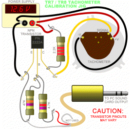
I plugged a cable into the sound card output and attached it to the very simple circuit shown above that can be made from a couple bucks worth of
parts from Radio Shack (or scrounged from that old tape deck sitting in the basement that you never get around to throwing out).
I connected a 12V power supply to the tach and fed it (the tach) the signal fom my PC. I set the program to output a square wave and fiddled with the amplitude and
duty cycle. I looked at the signal with an oscilloscope and the frequency counter. The square wave has a fair amount of 'ringing' but that didn't
affect anything provided the signal amplitude was high enough. I set it to put out a square wave with an amplitude of about 2 volts. That is what
the sound card puts out with things turned most of the way up (turn off any tone controls).
You don't want it much higher than that anyway, so don't run it through an external amp or anything. The duty cycle had to be set between
40 and 50 percent for proper operation over the entire RPM range.
It worked perfectly. A PC signal generator is extremely accurate. Here's how to set it:
Freq in Hz = 4 * RPM / 60 [for V8]
Freq in Hz = 3 * RPM / 60 [for V6]
Freq in Hz = 2 * RPM / 60 [for I4]
For example:
[V8}
500RPM = 33Hz
1000RPM = 67Hz
2000RPM = 133Hz
3000RPM = 200Hz
4000RPM = 267Hz
5000RPM = 333Hz
600RPM = 400Hz
7000RPM = 467Hz
Whenever you change RPMs, gently tap on the front of the tach a few times with a finger to get the pointer to settle properly.
Set the low RPM accuracy first by feeding in a 1000 RPM signal and adjusting it dead-on using the little white plastic zero-adjust lever directly opposite the circuit board.
THIS IS IMPORTANT TO DO FIRST !!!
Examine that weird looking metal 'fence' surrounding the meter movement. It has eight segments. When the pointer is aligned with
the 500, 1000, 2000, etc. marks on the dial, the drive coil is right next to one of the segments. If you are feeding in a signal for,
say, 4000 RPM and (after gently tapping) the pointer is reading a little high, bend the fence segment that lines up with the coil out a little.
Tap the dial again. If the pointer is a little low, bend the segment in. Tweak each segment until the tach calibration is acceptable.
If you don't have a 12V power supply, you can use a car battery and put a 1 amp fuse in the line to prevent disaster. Or you can pick up a
couple of quad AA battery holders when you are in Radio Shack. Wire them in series to get 12V. Or pick up a 'wall wart' power supply at a
thrift store for a buck. Get one that puts out DC at around 9 or 10 volts - they almost always put out a lot more than they are rated for
when they aren't loaded down heavily. If you find a 'switching' wall wart or brick (you can tell these because they seem far too light for
their power ratings), get one that is rated 11 to 14V. (Their regulation is much better.) You may have to load the switcher down with a turn
signal bulb because they sometimes won't work correctly unless enough current is drawn. Whatever you use, carefully check it with a voltmeter
before hooking up your tach. If you don't have a digital voltmeter, bite me! Sears regularly has them on sale for ten bucks; get one.
The diagram above shows what you need and how to hook it up. The resistors can be 1/4 or 1/2 watt or whatever. The transistor is an NPN 'small signal' type -
somethingsomething2222A, MPSA05, etc. The plug is a mini stereo headphone cable that fits the jack on your PC. Make sure you plug it into the
speaker/line/headphone out - not the input by accident (that's ten minutes of anxiety I'll never get back...) Another 4.7K resistor in place of the 2.2K should work, but I didn't try it.
Plug the cable into the PC.
Turn on the power supply.
Run the program.
(Square wave with 45 percent duty cycle.)
You may also have to adjust your PC mixer/volume controls.
Tweak away.
IF YOU HAVE ANY DOUBTS ABOUT YOUR ABILITY TO DO THIS WITHOUT BLOWING SOMETHING UP, DON'T DO IT!
| 