
TR7 ECU
This content originally published at our WWWedge site, on the Wedgelabs page(s) developed by Gene Thompson, and hosted at team.net. Gene Thompson retains all copyright for the material below, except where noted.
Just about the only internet site I could find with first-hand technical information was Tero Katajainen’s page (The Desperate Tuner) at http://www.students.tut.fi/~katajain/index.html
The original page no longer exists, but is mirrored in various places around the Web.
Many of his comments were rather ambiguous and the graphs often cryptic, so I spent some time searching for clarification. But in classic internet fashion, after that first tiny bit of genuinely useful information, all I could find was endless, virtually worthless comment and uninformed speculation about that original nugget.
I really hate that, so I rounded up a TR7 ECU and took a look for myself.
The Schematic
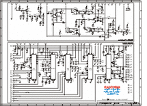 I drew up a schematic and two layout diagrams along with a system wiring diagram and put them in a four page PDF. Click on the small schematic at left to see it or ‘right click’ + ‘save target as…’ to download it.
The ECU has two circuit boards inside, so the schematic is divided into two parts. The layouts show x-ray views of each board. Orange is top, green is bottom; darker colors for traces denote grounds. The components that are attached to posts above the board are colored red.
I did not take apart the large hybrid modules – they are shown simply as rectangles in the schematics. Keep in mind that the schematic and layout are only for the US spec Triumph TR7. When the board is used in different cars, it may have different hybrid modules and may be ‘loaded’ very differently.
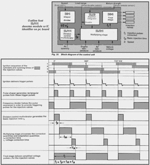 The diagram at left (click on it for a larger version) is from a Bosch pamphlet that explains the overall operation of the ECU. I added the PC board identification of the various modules that do the heavy lifting.
Please note that the output waveforms produced by the rather sophisticated (compared to the TR8 ECU) output current control circuity are not shown in the diagram.
So, armed with the schematic and what little info I could glean from a couple of Bosch pamphlets, I once again took a stab at deciphering the Desperate Tuner’s page. As near as I can tell and taken with a grain of salt, these are the high points:
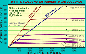 For performance, these two seem most important:
- R106: Rev limiter. Decreasing value raises rev limit. TR7 ECU = 620K (in parallel with R110, 120K)
- R103: Sets enrichment vs. RPM. Increasing value gives greater enrichment as RPMs increase. TR7 ECU = 620K (in parallel with R104, 47K)
- R237: Sets upper bound for airflow signal influence during cranking. TR7 ECU = not used (in parallel with R238, also not used)
- R239: Sets lower bound for airflow signal influence during cranking. TR7 ECU = 47K (in parallel with R240, 6.8K)
- R758: Fuel cut-off speed (for coasting-cutoff).
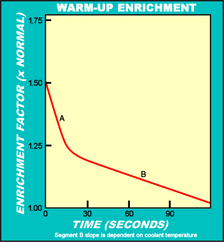 These shouldn’t need tweaking unless large engine changes have been made and it stumbles during warm-up.
Warm-up enrichment modification:
- R616: Part-throttle and post-cranking warmup enrichment only work below a coolant temperature specified by R616. TR7 ECU = 470ohms (in series with R615, 1.3K)
- R617: Post-start and temp. warmup enrichment amount. Smaller value = less enrichment. (Section A on graph) TR7 ECU = not used (but is in parallel with R618, 36K)
- R306: The timing of post-start warmup enrichment. Bigger value = longer enrichment (Section A on graph). I’m pretty sure he made a mistake reading the PC board. I think it should be should be R309. TR7 ECU = 270K
- R621: Part-throttle warmup enrichment amount Smaller value = more enrichment. (Section B on graph) TR7 ECU = 130K (in series with R620, 130K)
- R624: Part-throttle warmup enrichment decay speed. Smaller value = faster decay. (Section B on graph) TR7 ECU = 91K (in parallel with R625, 18K)
Miscellaneous Information:
The part-throttle enrichment, post-cranking enrichment and and coasting-cutoff are on the Aux board.
The wide open throttle (WOT) enrichment triggered by throttle switch is fixed at ~9%.
The injection time is also subjected to correction needed to compensate the different injector opening times. This is governed by R345.
TR7 ECU = 6.2K (in parallel with R346, 51K)
The injectors are opened with ~4A/injector. After ~.5 mSecs the total current is held at a current level determined by R408 (Typ. ~2A).
TR7 ECU = 1.8K (in parallel with R407, 33K)
The formula for two resistors in parallel is Rtotal = (R1 x R2) / (R1 + R2)
